Here is some very detailed technical information about the WxShield. All specifications below are typical or estimated, and are NOT guaranteed.
For those who may be struggling with the source code published by Bosh which converts the BMP085 readings into pressure, here's a link to a document which offers another way to perform these calculations using floating point math and is much less complicated than the code from Bosch (which is intended for embedded systems that don't have the luxury of floating point math).
The Freescale receiver we're using in the version 2 shield has an IF (noise) bandwidth around 400kHz. We've added a SAW filter followed by low-noise preamp to the input to improve sensitivity and out-of-band signal rejection. The result should have a noise figure typically between 3 and 8dB (the range in values is due to part-to-part variations in the SAW filter and Freescale receiver). This translates to an input sensitivity (assuming 10dB SNR) of between -109 and -115dBm.
Actually, there is a bit of guess work here as Freescale does not specifically state that the noise bandwidth of their reciever is 400kHz, but sensitivity measurements we've made seem to validate these numbers.
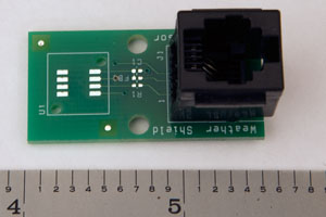
Here's a close-up photo of the remote board, which is quite small. The largest thing on it is the RJ14 jack for
the telephone extension cord connecting it to the WxShield. The board is 3/4 by 1-1/2 inches and with the
RJ14 jack it is about 3/4 inches high. On the left side you can see the pads for soldering the SHT15 sensor
and there are two holes there to mount the filter cap to protect the sensor. Click on the photo for a larger image.
The only other parts on this board are a ferrite bead and capacitor to filter the power to the SHT15 sensor, and a 240-ohm resistor in series with the data line to reduce ringing on very long remote cables.

Inexpensive antennas may be purchased, or built.
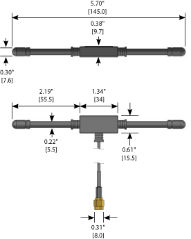
Pictured at left is one such specimen sold by Linx Technologies. It is available with a 6-1/2 or 15-foot cable for around $12US from several electronics parts distributors (e.g. Digikey and Mouser). Be sure to get the standard SMA connector option -- the reverse polarity SMA (sometimes called "RPSMA") will not work.
Part numbers are ANT-433-MHW-SMA-S (short cable) and ANT-433-MHW-SMA-L (long cable). We've tried this model and it works quite well with the WxShield. It is small and unobtrusive, plus the long cable provides a lot of flexibility in antenna placement.
Another option is a simple 1/4-wavelength vertical antenna design which is easily fabricated from a right-angle SMA connector and some 12 or 14-gauge copper wire. Instructions for building such an antenna are included in the WxShield user manual.
This antennas design has been tested on an obscenely expensive piece of equipment called a Vector Network Analyzer. All antennas have been individually tested against a performance metric called return loss. Each antenna has been verified to have a return loss of at least 8dB (at 433.92MHz into 50Ω). This means that at least 84% of the power received by the antenna is delivered to the receiver. The WxShield receiver itself has a typical input return loss of 25dB or better (at 433.92MHz) which means that the antenna's return loss will be the dominant factor in received power transfer.
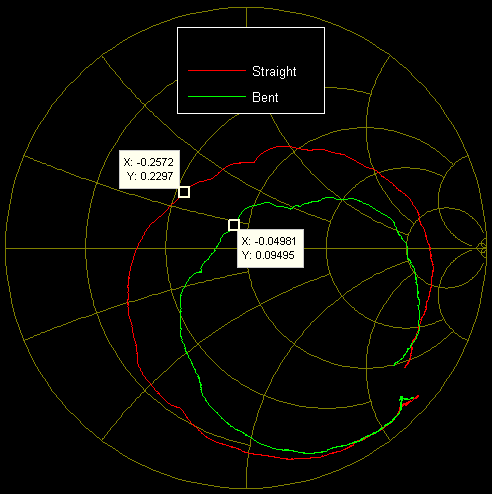
If the three ground radials are bent downwards slightly (perhaps about 2 inches or 5 cm below the horizontal plane at the ends), the impedance match is markedly improved. Measurement plots below include one antenna with perfectly horizontal ground radials, and one with the three radials bent slightly downwards.
Here are a couple of measurement plots on one of the antennas. The first one below is the input impedance on a Smith chart. The full frequency range of this plot is from 234MHz to 634MHz, and the markers are placed at the operating frequency of 434MHz. Although this is plotted on a 50-ohm smith chart, the displayed values are actually real and imaginary parts of the reflection coefficient, k. The actual input impedances are:

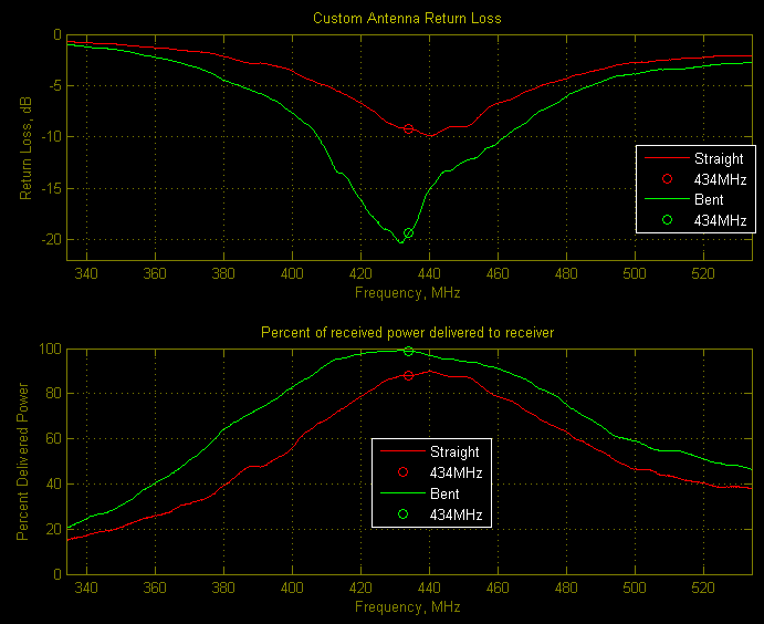
And here are two plots showing return loss in decibels, and what this means for power transfer from antenna to receiver.

It's easy to see how much difference it makes when the ground radials are bent down slightly. On one hand, return loss increases significantly, by about 10dB. On the other hand, this improvement only makes a slight difference in the percentage of power delivered from the antenna to the receiver. The bottom line is that it probably will not make a noticeable difference, but it won't hurt to try it if there are one or more sensors with very weak signals.
One final caveat about these measurements is in order. Data was taken with the antenna at the end of an 18-inch piece of coax held horizontally, and the antenna was at least 3 feet away from any other objects. The actual return loss seen with an antenna in an actual installation may vary significantly -- depending on nearby objects. This is more sensitve to metallic objects, but non-metallic objects can also affect the results. Having said all this, trial and error is the best way forward. If good results are not acheived, try moving the antenna in relation to nearby objects until better results are obtained.

