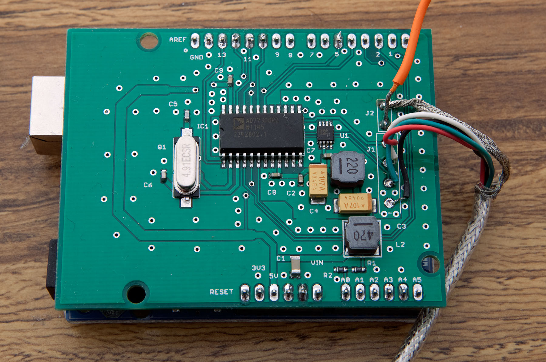
Assembled load cell shield (click image for larger photo)
Assembled load cell shield (click image for larger photo)
We've added some missing items to the BOM, fixed some incorrect part numbers and changed the inductor(s) from Murata parts to Coilcraft. There are new Gerbers here as well as schematic and board files. Thanks to volunteer contributor "JW" for helping with these changes.
This project is a shield for Arduino that can convert the low-voltage analog output from a load cell to a stream of digital data. An integrated circuit made by Analog Devices provides a 24-bit analog-to-digital conversion.
The unit photographed here is connected to a load cell sold by Omega.com, the LCEB-25. This load cell has a 25 pound (11kg) capacity. The load cell shield can measure weights down to less than 1 gram using this 25-pound load cell. The circuit is capable of measuring such small voltages (less than one microvolt) that it helps to mount the Arduino/shield assembly inside a metal box to prevent stray electrical fields from adding noise to the measurements. It is also important to ground the load cell cable shield to the load cell shield board and to also ground the shield board to the metal enclosure.
The design uses mostly surface-mount components. Passives smaller than 0603 size were avoided. The Analog Devices ADC can be hand soldered; the precision voltage reference may be a challenge for hand soldering. Not impossible however. This shield photographed here was assembled using hand-applied solder paste and a toaster oven.
The ADC from Analog Devices has input ranges from 10mV to 80mV full scale. The load cell bridge is excited with 2.500 volts. Any load cell that outputs between 10 and 80mV full scale with a 2.5V excitation will work with this shield. As an example, the LCEB-25 nominal output is 3mV per volt of excitation at full scale. With a 2.5V excitation, it will produce 3mV * 2.5V = 7.5mV output. This is not too small for the 10mV input range of the ADC and works fine.
The Arduino sketch compiles with Arduino 1.0.3 but it is necessary to set the sketchbook location (File...Preferences) to the directory containing the libraries and LoadCell folders. After changing the sketchbook location, the Arduino compiler window must be close and re-started.
In the LoadCell.ino sketch file, there is a constant declared called "loadCellGain". When the LCEB-25 load cell was purchased it came with a calibration document indicating the exact output voltage gain. In this case, the value was 3.23581mV/V at full scale (25 pounds). You will see this number set as the load cell gain. This must be changed to the proper calibration value for your load cell. Other values may need to be changed in that section of the software as well, depending on your load cell.
Click here to download the new zip file containing a license, bill of materials, Eagle CAD files, a PDF schematic, data sheets, and software for this project.
Click here to download the original zip file containing a license, bill of materials, Eagle CAD files, a PDF schematic, data sheets, and software for this project.

